Stock CDI
The stock CDI system consists of a sealed box mounted under the gas tank, on the left side, close the steering stem. It uses 3 pickups, and takes it's power directly from the stator. The stator has two odd coils, which provide 100V and 200V respectively.
The CDI is powered by the 100V coil, the 200V coil only provides power higher up the rev range. It uses a clever mechanism of voltage meshing to advance the ignition. According to "The Design and Tuning of Competition Engines", a similar system was already being tested by Maserati in the 50s. I included an excerpt below.
This system is very complex, yet non-adjustable. The coils on the stator are notorious for going bad, leaving you stranded, or limited to approximately 5000rpm (if the second coil fails).
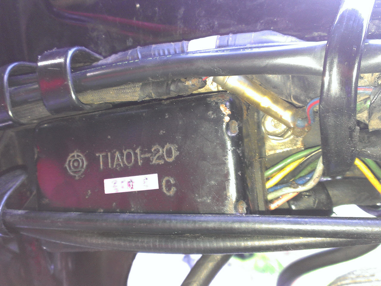
Stock CDI box
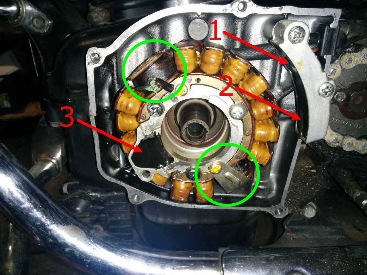
The stator with the pickups (1,2,3) indicated in red, and the CDI coils circled in green
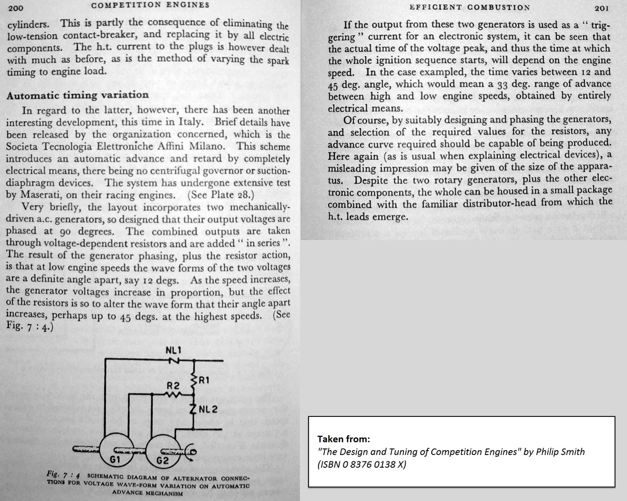
An brief explanation of the stock design
Ignitech CDI
Driven by curiosity, and a bit by the poor fuel mileage, I went looking for a programmable CDI adapted for this old bike.
Enter Ignitech, which sells just that. They specialize in CDI and inductive ignitions for (older) motorcycles. As opposed to the stock CDI, their products are powered straight from the battery, and are quite adaptable to different setups.
Having a programmable ignition is nice, but I wanted to take it one step further. These ignitions are all prepared to take input from a Throttle Position Sensor, which is used to create a 3-D "advance map" as opposed to a 2-D "advance curve". This allows ignition advance to be adjusted depending on the bike's actual load, which makes for smoother driving and better fuel economy.
Unfortunately I lack metalworking skills, and I did not feel comfortable modifying the carburetors for a TPS sensor, or adding a remote TPS setup, with added cable clutter.
The next possible option was to use a Manifold Air Pressure sensor, which does basically the same as a TPS sensor, but is generally more accurate. Despite the fact that both types of sensors generally output a voltage between 0-5V, a MAP sensor provides a much higher resolution signal and cannot be directly connected to TPS input, it would not be stable enough. I had the option of buying a DC-CDI-2P unit, and hook up a MAP sensor to the TPS input, with an inline filtering circuit to smooth out the input, or I could buy the DC-CDI-2P-Race unit, which had more options, more maps, and readily took the MAP sensor input.
I chose the "race" CDI, and bought the MAP sensor to go with it. As soon as I ordered, I started to look for possible ways on how I could hook this all up. I was in way over my head.
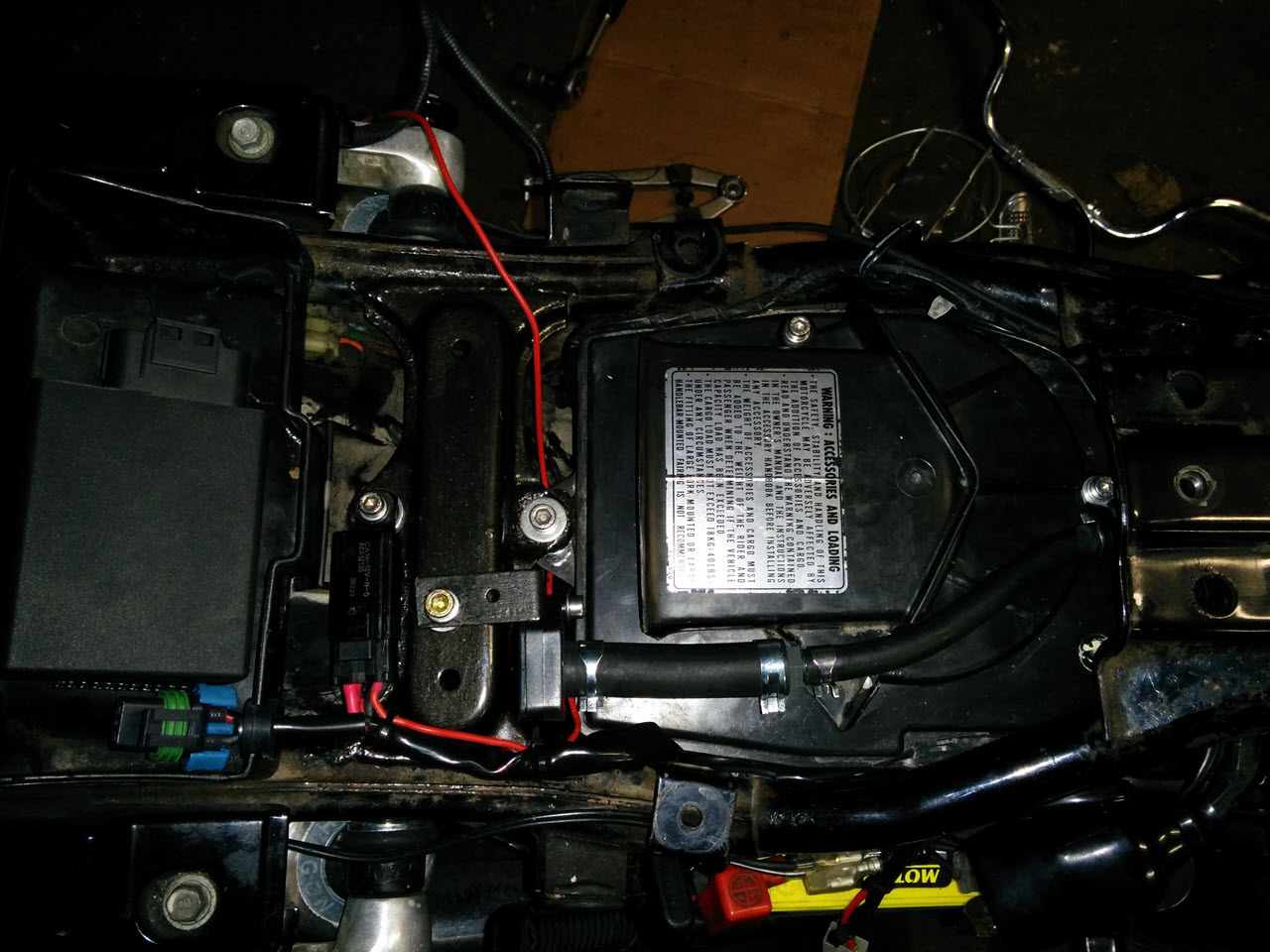
Placement
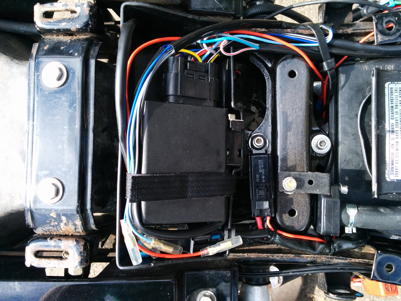
I read reports of some of the Ignitech boxes being effected by EMI/RFI. Placing the box in the original location, near the copper spark plug wires, was not an option for me. I like the glovebox above the rear light, and wanted it free for future use, so the only other option was in the toolbox. I gave the auxiliary fusebox a different spot, and fastened the CDI with a piece of 3M "Dual Lock" tape, and a velcro strap. The latter is more intended to keep the cabling in place, then acts as a second fastening mechanism.
For power, I used the same 16A relay that switches one of the circuits in the AUX fusebox, with an un-fused wire going straight to the CDI.
As an additional security measure, to promote longevity and trouble-free running, all of the connectors going towards the CDI are Delphi Weatherpack sealed connectors. Though bulky, they are easy to crimp, easy to connect and maintain and overall pretty foolproof.
Unfortunately some stuff got lost in translation while communicating with Ignitech, so the wire lengths in the ignition harness were completely wrong. Some way too long, some way too short. Since the DC-CDI-P2 Race uses a special waterproof connector, I was in for a difficult job. I order some wiring, a spare JAE MX23A26SF1 connector and the associated terminals, and spent half a day meticulously rewiring the connector. They are a pain to crimp and put together, I needed a lot of practice.
The CDI fits snugly inside the toolbox
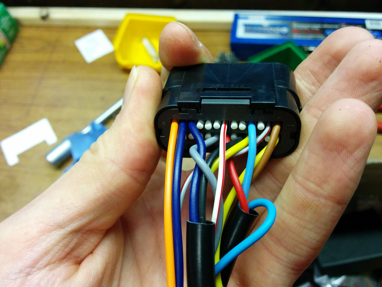
JAE MX23A26SF1 26-pin IP67 waterproof connector
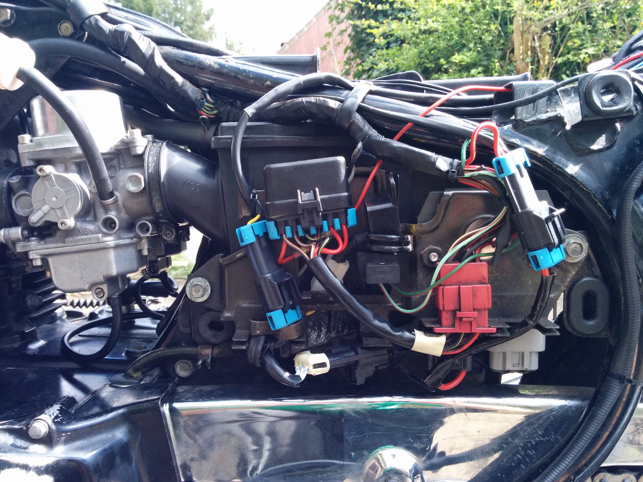
The wiring under the left side cover
Coil connector
MAP sensor
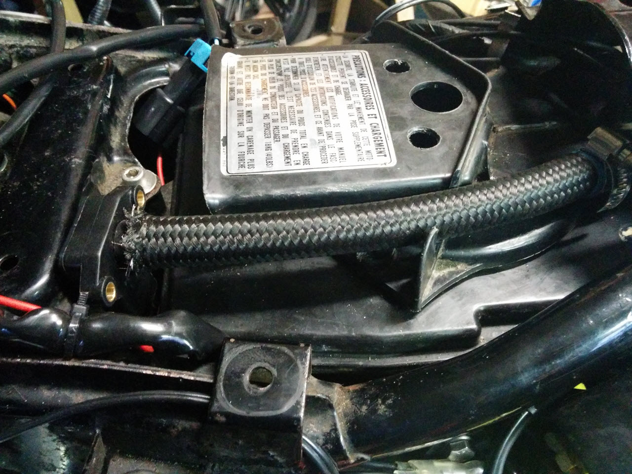
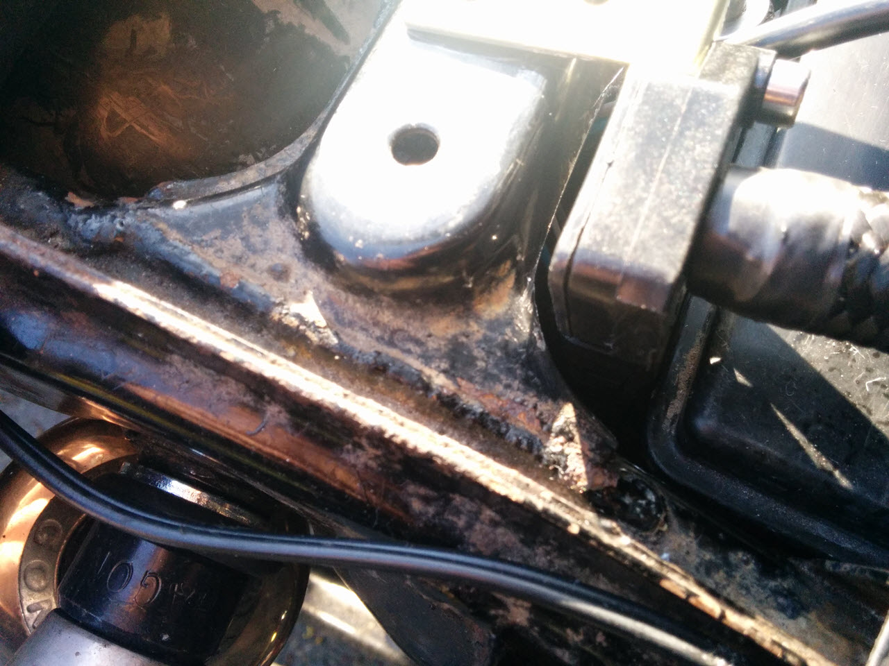
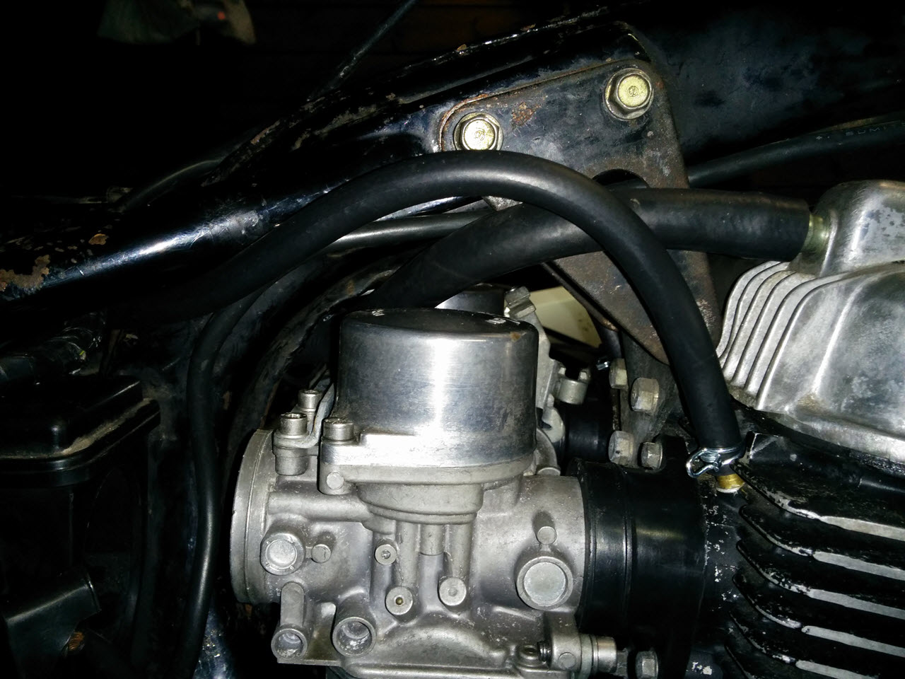
I decided to take my vacuum signal from the two brass plugs I added to the cylinder intake ports. I wanted to hook them up in a Y-configuration to the MAP sensor, but the sensor from Ignitech had a completely different hose diameter. I contacted a local company, TRAXX racing, that specializes in hoses and lines for racing applications. They were very patient and friendly, and hooked my up with an initial setup. Though extremely pretty, it was a bit too bulky to fit under the seat. I was able to return their Y-piece and used a plastic Y-connector to connect everything cheaper, and with less bulk. I did use their hoses, and will talk to them again if I start to tweak this setup some more.
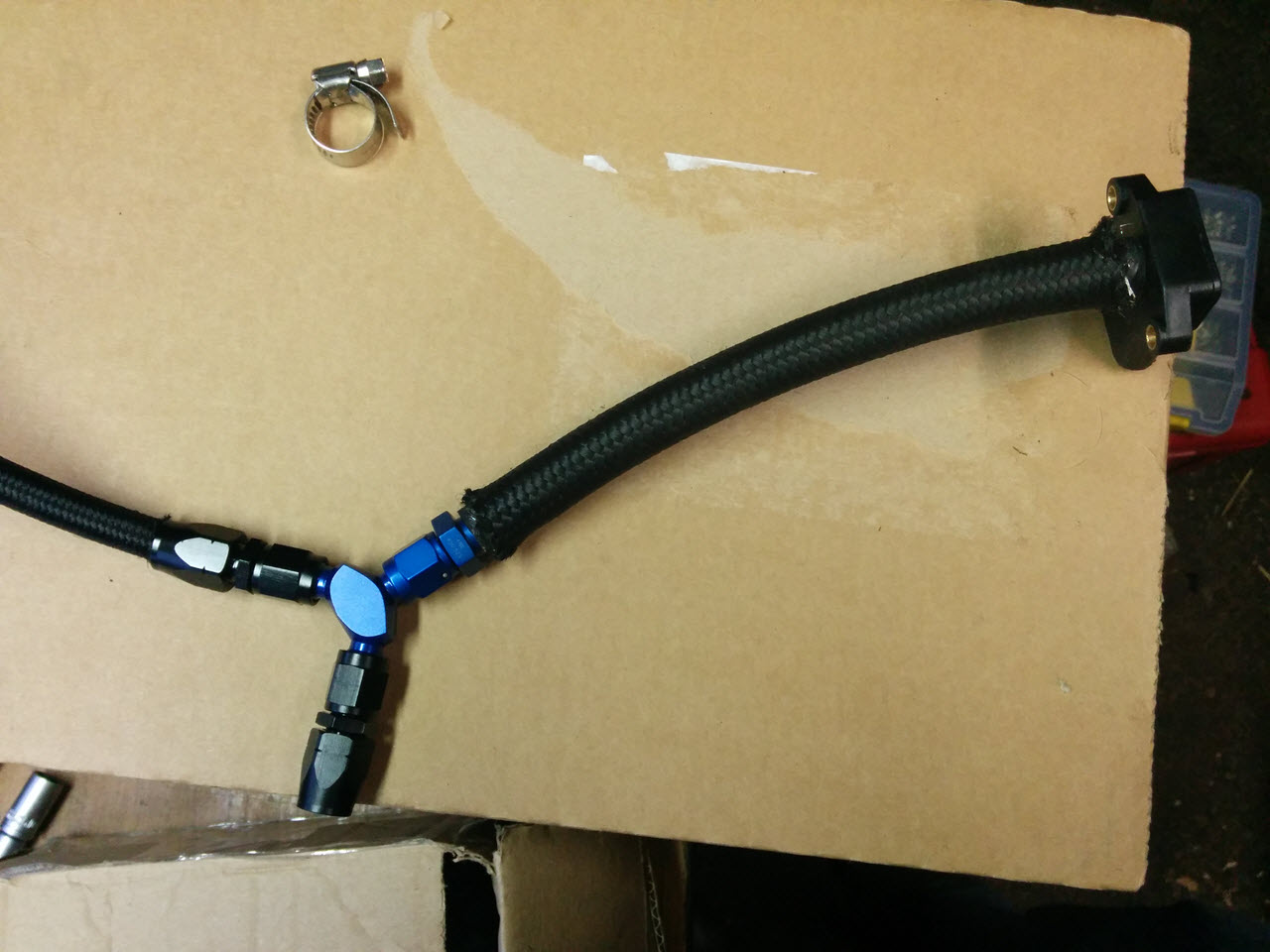
The initial hose setup
After a trying a lot of places, this seemed like the most logical place for the MAP sensor. I cut the airbox cover to make room for the hoses, a spare cover is shown here
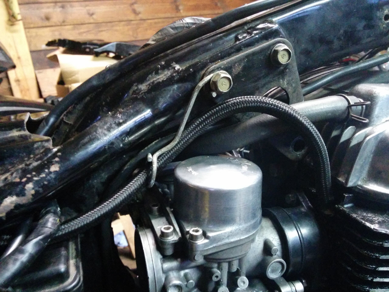
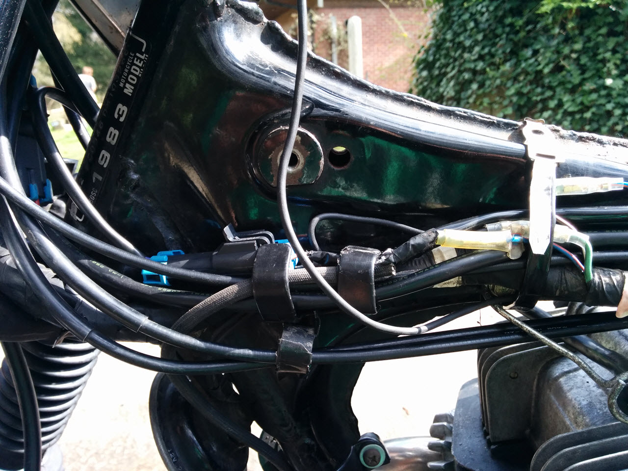
The hoses were to be routed under the rear tank bolt, into the Y-piece and to the MAP sensor from there
Tried several fastening options before settling on a bracket
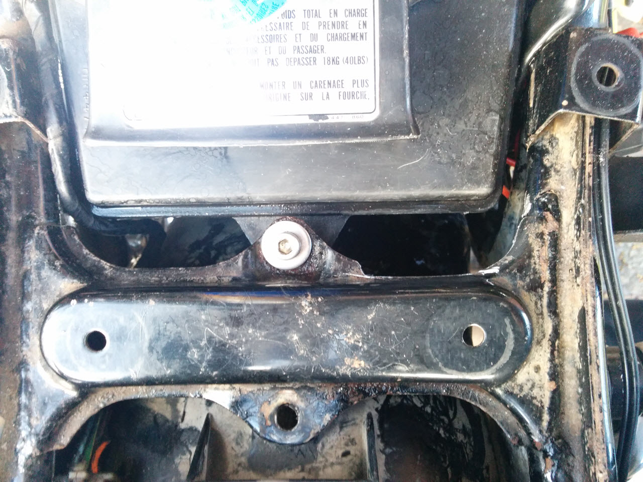
The ridge on the frame was filed down to prevent the sensor from rubbing and to ease fitment. It would have been a very tight fit otherwise
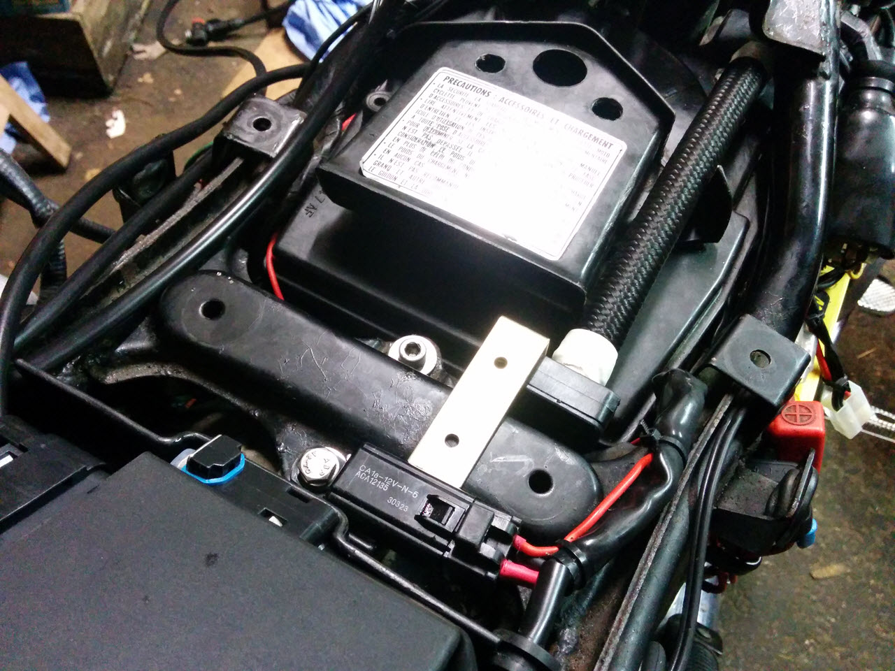
Test fitting the sensor with the modded frame
Drilled and painted the frame and bracket. I used washers on the bracket to provide some swivelling/wiggle room for the sensor
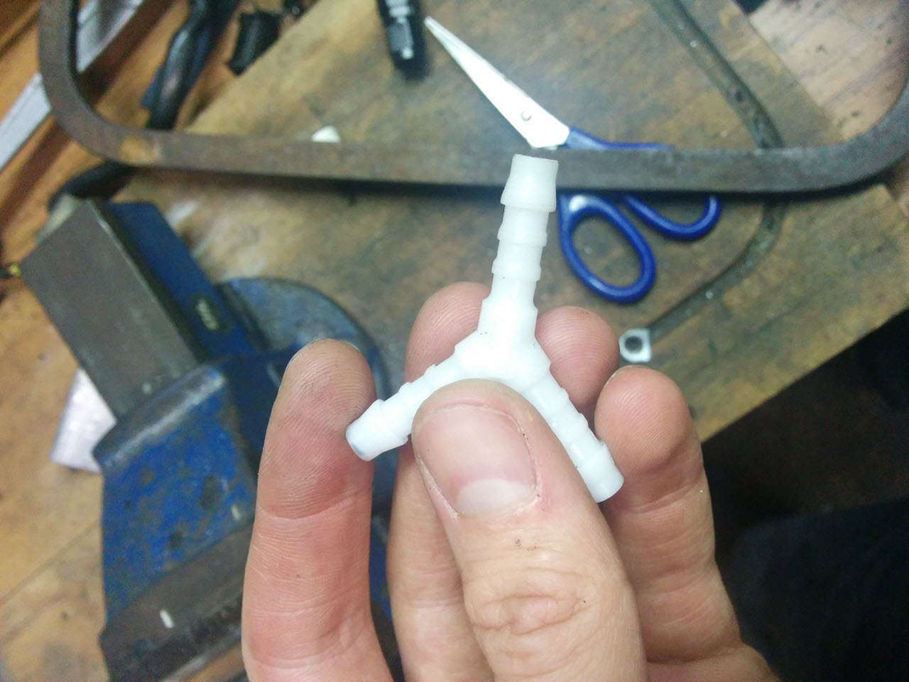
The plastic Y piece is a fraction of the cost and uses no space
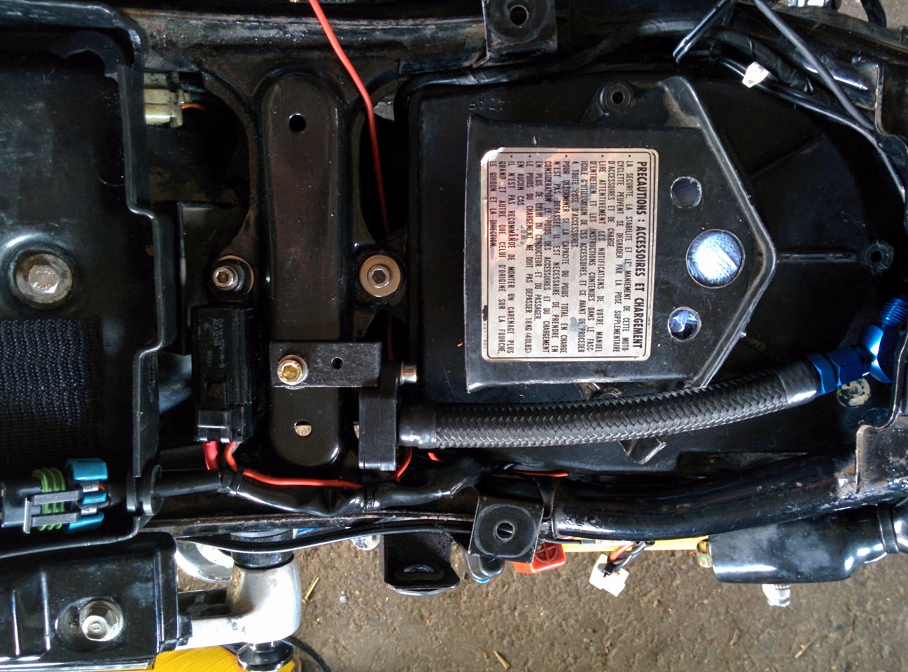
I was able to fasten it with the rear airbox cover bolt
The hoses were to be routed under the rear tank bolt, into the Y-piece and to the MAP sensor from there
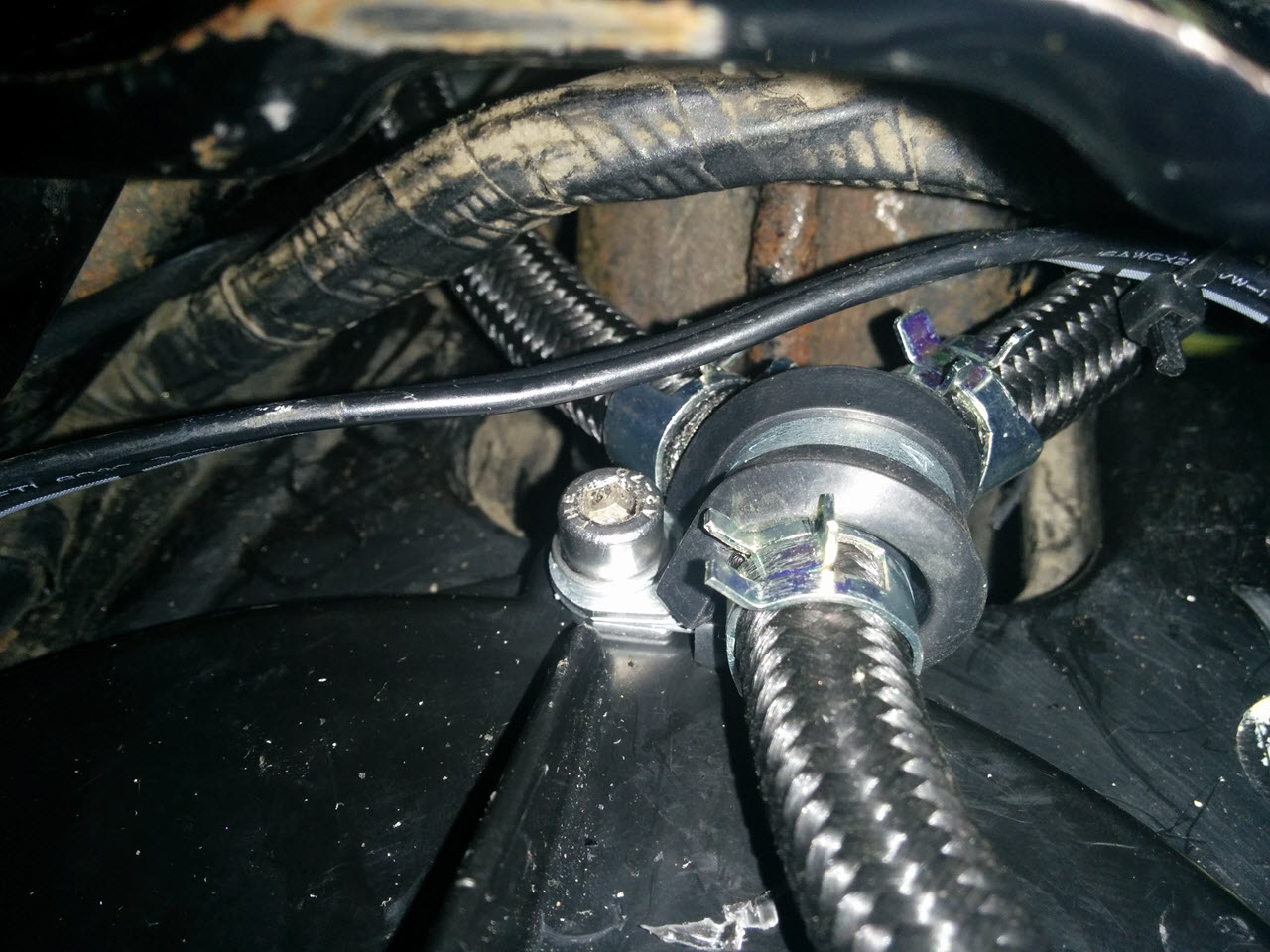
This is the near-final setup, this time with smooth hoses, as they are easier to work with
The hoses make a smooth bend and are hard to spot with the tank mounted
Coils and plugs
The bike still had the original coils and plug caps. After changing every other aspect of the ignition, it was only normal to swap the coils too. I originally intended to use a GM coil pack, this is also a very well documented, easy and very cost-effective mod. The downside with the GM coil is that they are huge, so mounting them is tricky, and neatly routing the spark plug wires is even harder. I opted for an Ignitech coil pack instead. I still needed to fabricate a bracket, but the coil pack is way smaller and easier to fit. I still need to do something about that awful blue color though.
The original plugs were NGK D8EA. Since I could not guess the age of the spark plugs when I bough the bike, I bought a set of NGK "iridium" plugs, DR8EIX. These spark plugs, however, have a built-in resistor. This, in combination with the 5K Ohm resistor caps, makes for a weaker spark. I used the iridium plugs on my other bike and have currently fitted a set of Denso non-resistor plugs.
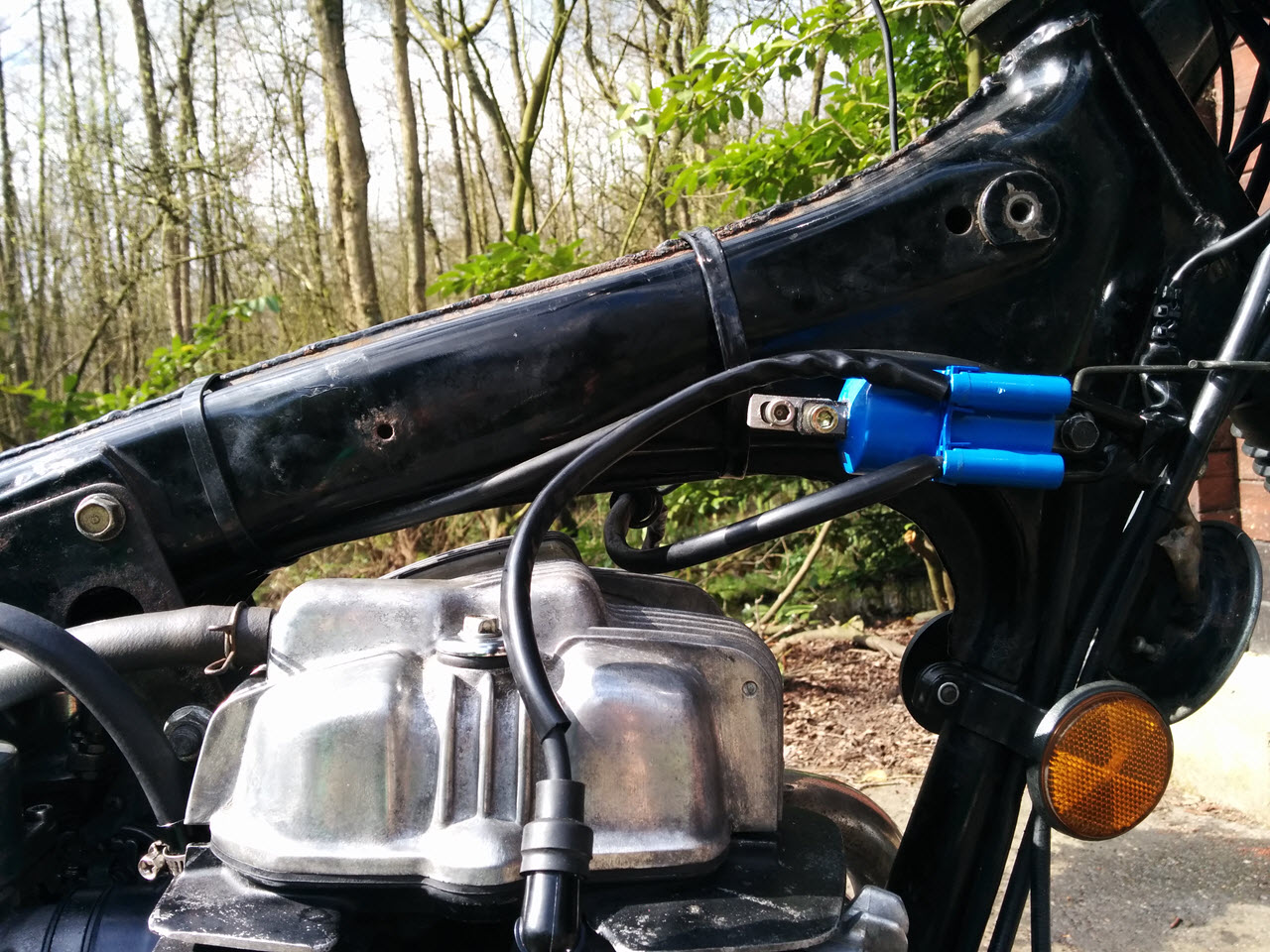
The Ignitech coils and bracket. You can just see the wire bracket I used to keep the left spark plug wire from resting on the cam cover.
Add-on box
While I was rewiring the JAE connector for the Ignitech box, I took the opportunity to add wires for inputs 2 and 3 (input 1 is the kill switch), and a potentiometer. The inputs would allow me to switch maps, set a rev limiter or decrease the timing on the fly. The potentiometer allowed me to advance or retard the timing on the fly. To make use of these extra connections, I built a small box with an automotive switch and a potentiometer.
The installation is documented, but how it works is not. You need a linear potentiometer with a range of 1-10K Ohm. The setup works as follows:
- Terminal 1 is connected to +5V (sensor power supply, pin XX on the JAE connector
- Terminal 2 is connected to the potentiometer input, pin XX on the JAE connector
- Termimal 3 is connected to sense ground, pin XX on the JAE connector
If you divide the potentiometer's working range with a scale from 1-10 (as I did), the potentiometer's "neutral" point is at 5. Turning it to 6 will increase whatever option you selected, turning it to 4 will decrease it.
I was initially planning to use this potmeter to finetune my mapping, but due to the complete lack of experience with ignition timing, I did not use it yet. I use the switch to change maps on the fly, and that has come in handy a lot.
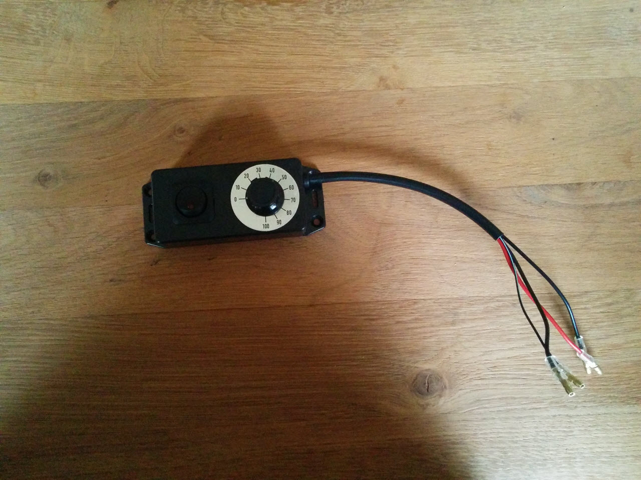
The finished "tune-box"
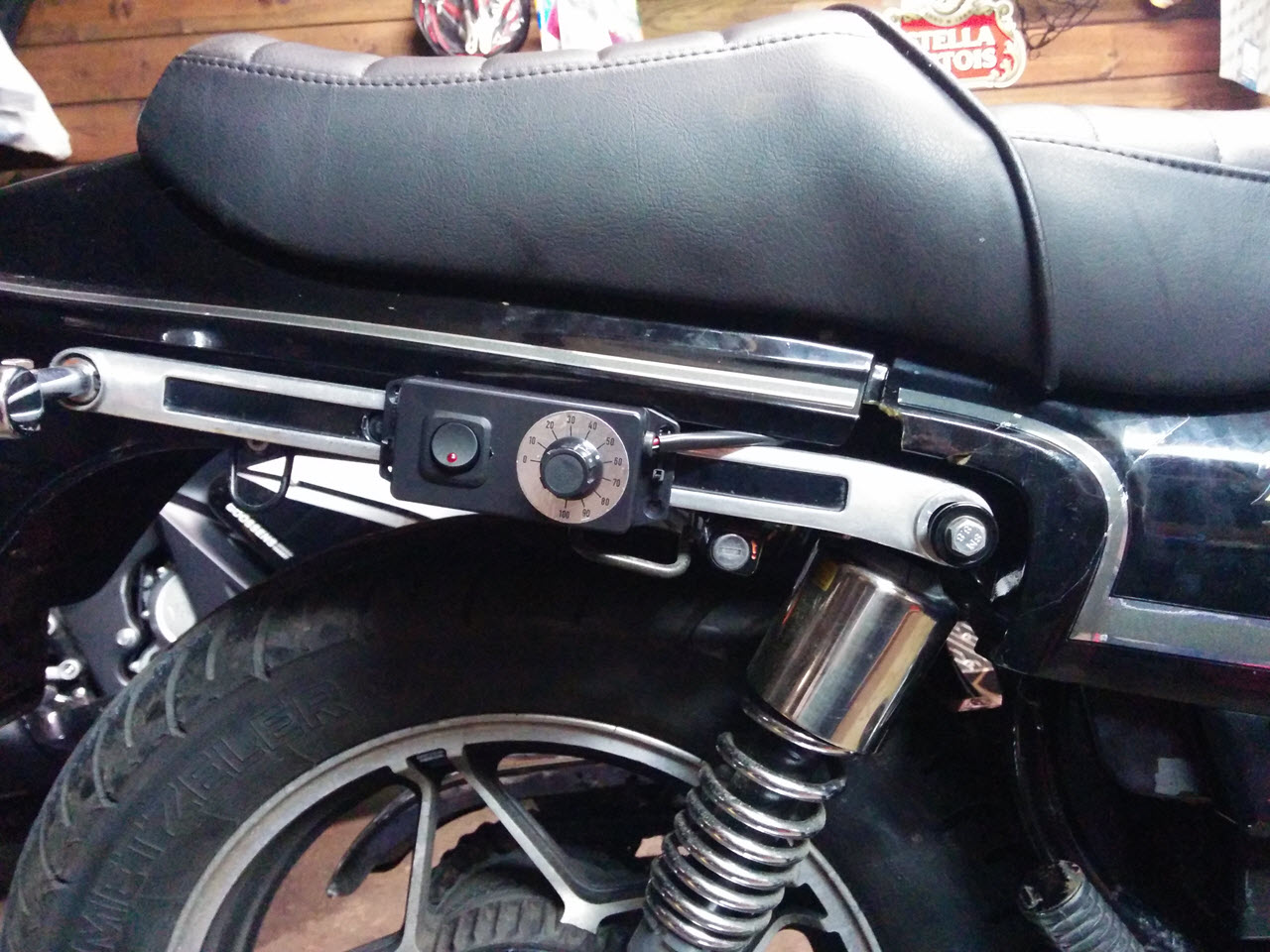
Mounted to the rear grip bar. It's not rain-proof so it cannot be permanently mounted
Tuning
With all of the hardware in place, I could start tackling the ignition map. Having no experience, and unable to find practical literature on the subject, I was quickly stranded.
I did find an extremely informative page on digital ignitions, advance and load mapping, at Gill Instruments, be sure to check it out.
As mentioned, the stock ignition curve is a 2-D curve. Nobody really knew the shape of the curve, just that full advance would be 42 degrees. The Ignitech boxes are notorious for being shipped with a very lazy advance curve. They clearly don't want anyone blowing holes in their pistons with their ignition systems. With no baseline and only conservative settings at hand, I resorted to Ruud Frederiks and his dyno to create a map.
Plagued by weird fuel delivery from the VB22 carburetors, and due to me not gapping the new Denso plugs correctly, dyno time was limited, and I ended up with a better, but still very conservative map.
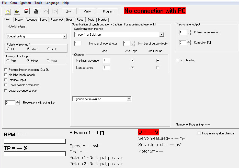
An overview of the pickup settings
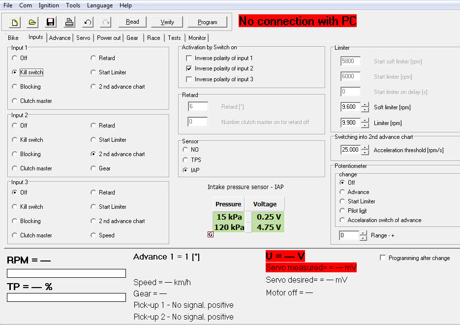
Lots of possible input options
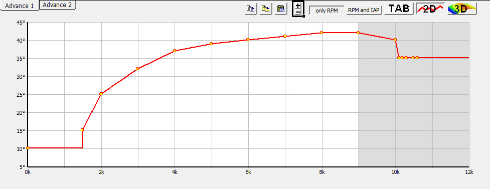
This is a representation of the stock curve in the Ignitech software, an average of measurements taken from 3 different stock CDI boxes by Jim O'Brien

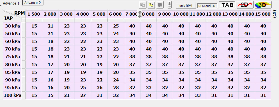
The curve from Ignitech, in the programming screen
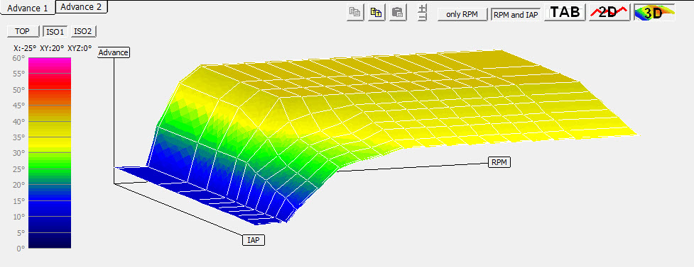
ISO-1 view of the Ignitech map
The map that was cobbled together on the dyno, not optimal
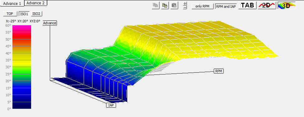
ISO-1 view of the dyno map