AGM Battery
I got rid of the stock battery and switched to a MotoBatt AGM battery. A no-brainer, because of the huge increase in cranking amps, and no measurable capacity loss during the winter months.
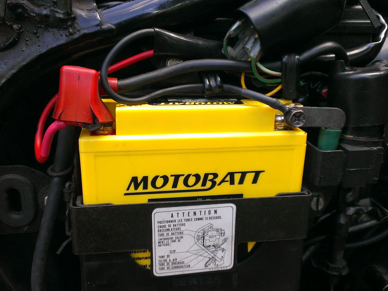
It is little higher than stock, but fits perfectly
Fusebox mod
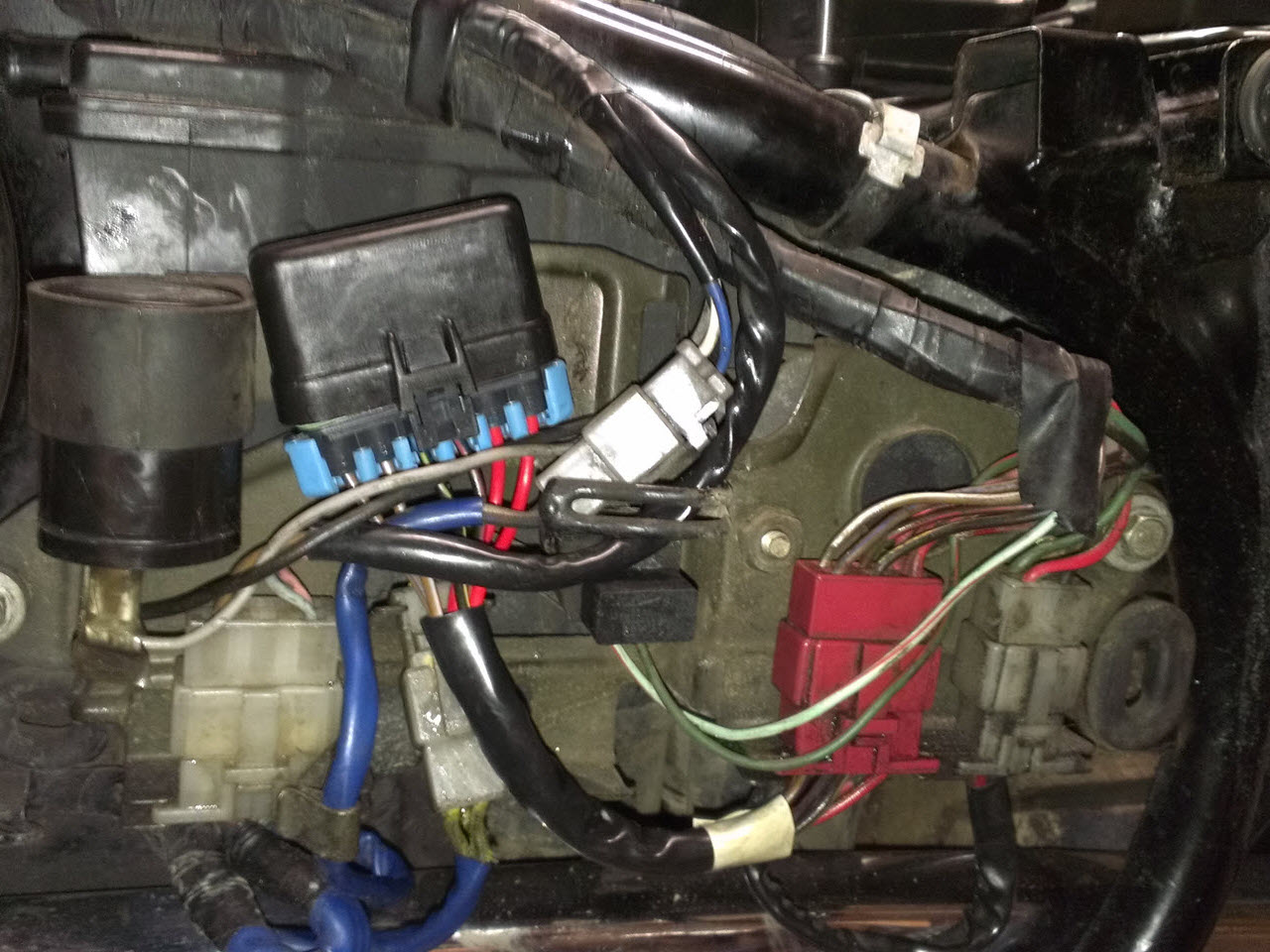
The bike still used glass tube fuses, and there was no means to connect additional equipment. I changed the stock fusebox with a Metri-Pack 3-fuse sealed fusebox, desiged for standard ATM fuses, and added a second fusebox to power additional equipment. I cut up the stock fusebox, saving as much wire as possible, while keeping the stock connector, for plug&play installation.
I used a decent crimper from vintageconnections.com, a ratchet-type crimper designed to crimp all kinds of insulated and non-insulated wire connections. Awesome piece of kit, and allows unskilled people to make decent crimps!
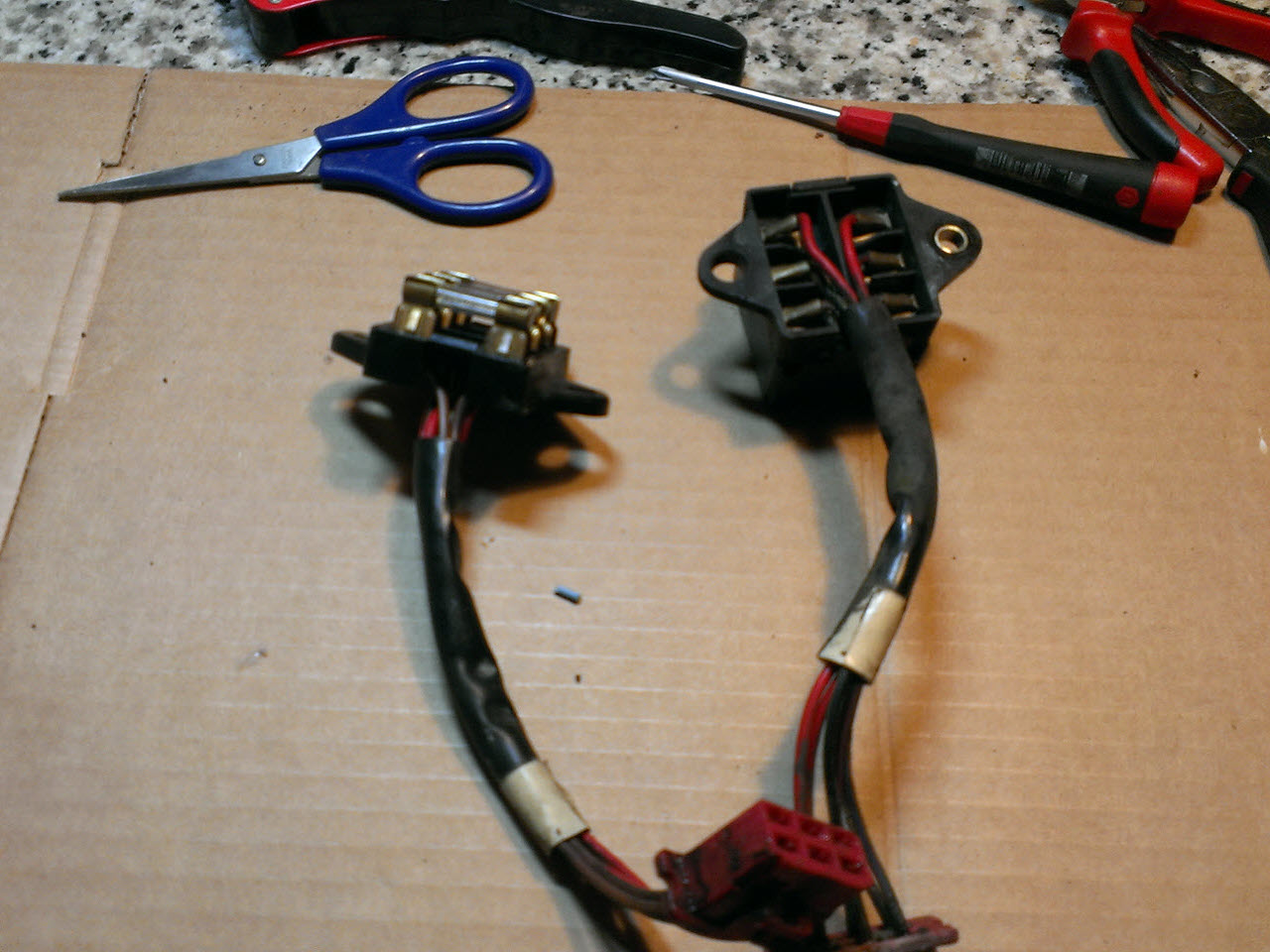
I cut up the best box, and used the other one as a pattern
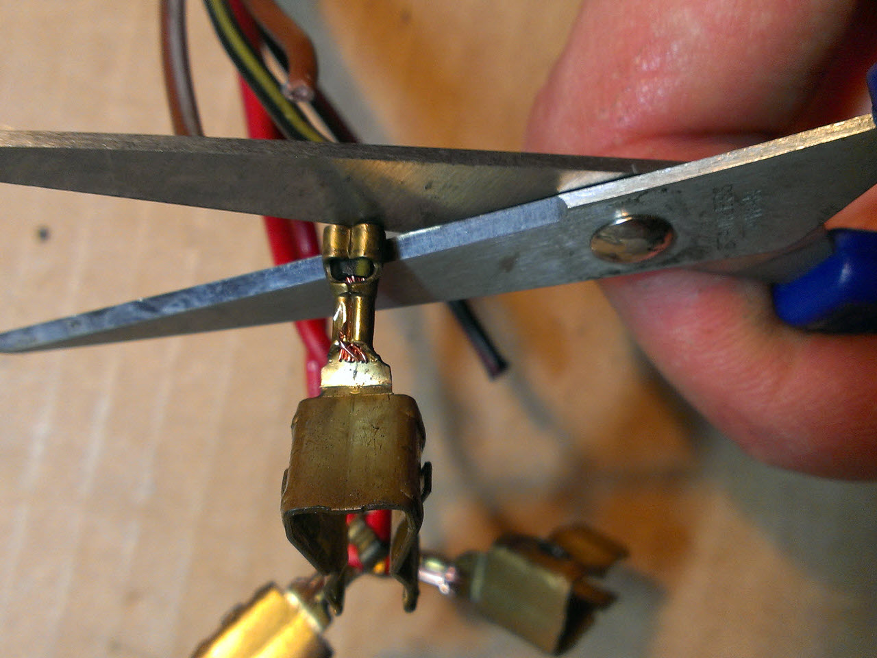
Removed the blades for the glass fuses
First try with the crimper, still learning
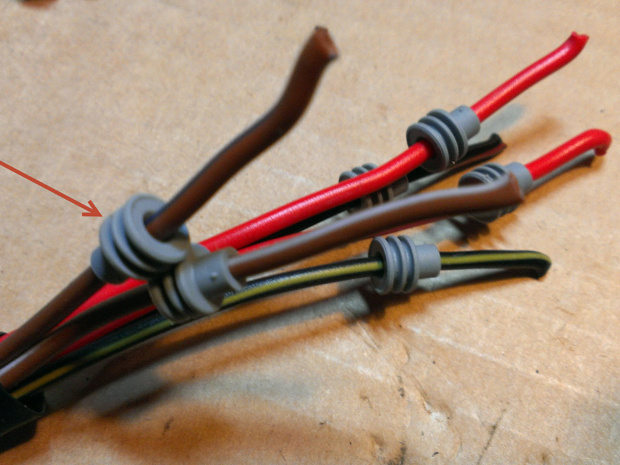
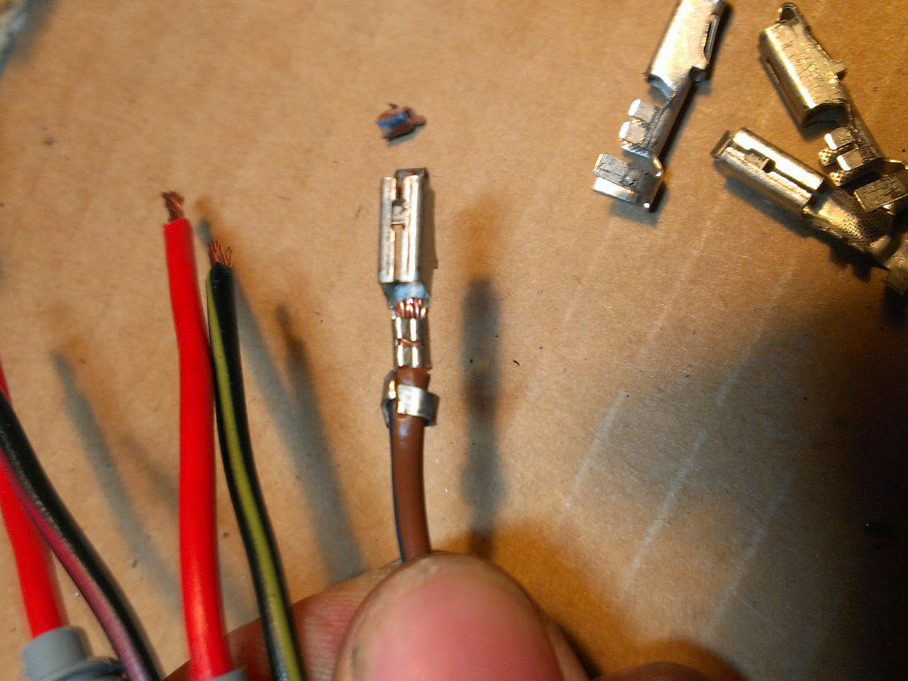
Normally the seals are crimped in. Something I did not know at the time. The arrow points to the seal that was mounted in the wrong direction
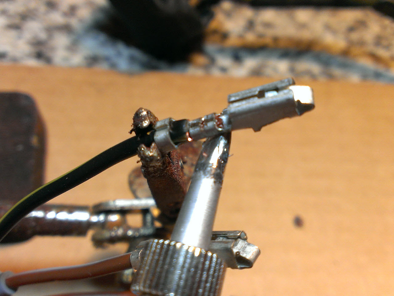
I soldered the connections to make them foolproof
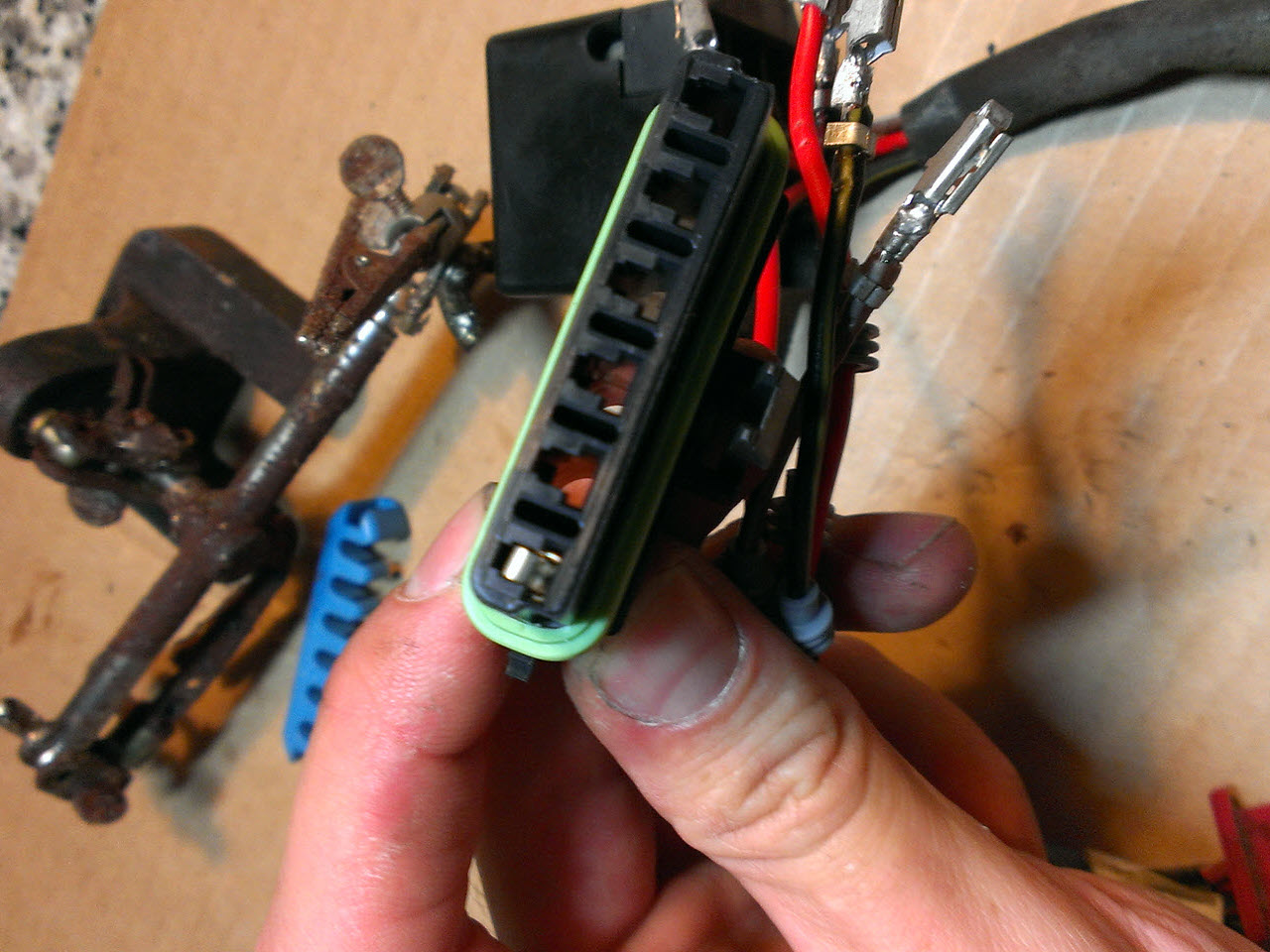
First terminal installed, you can see how they will hold the blade fuses
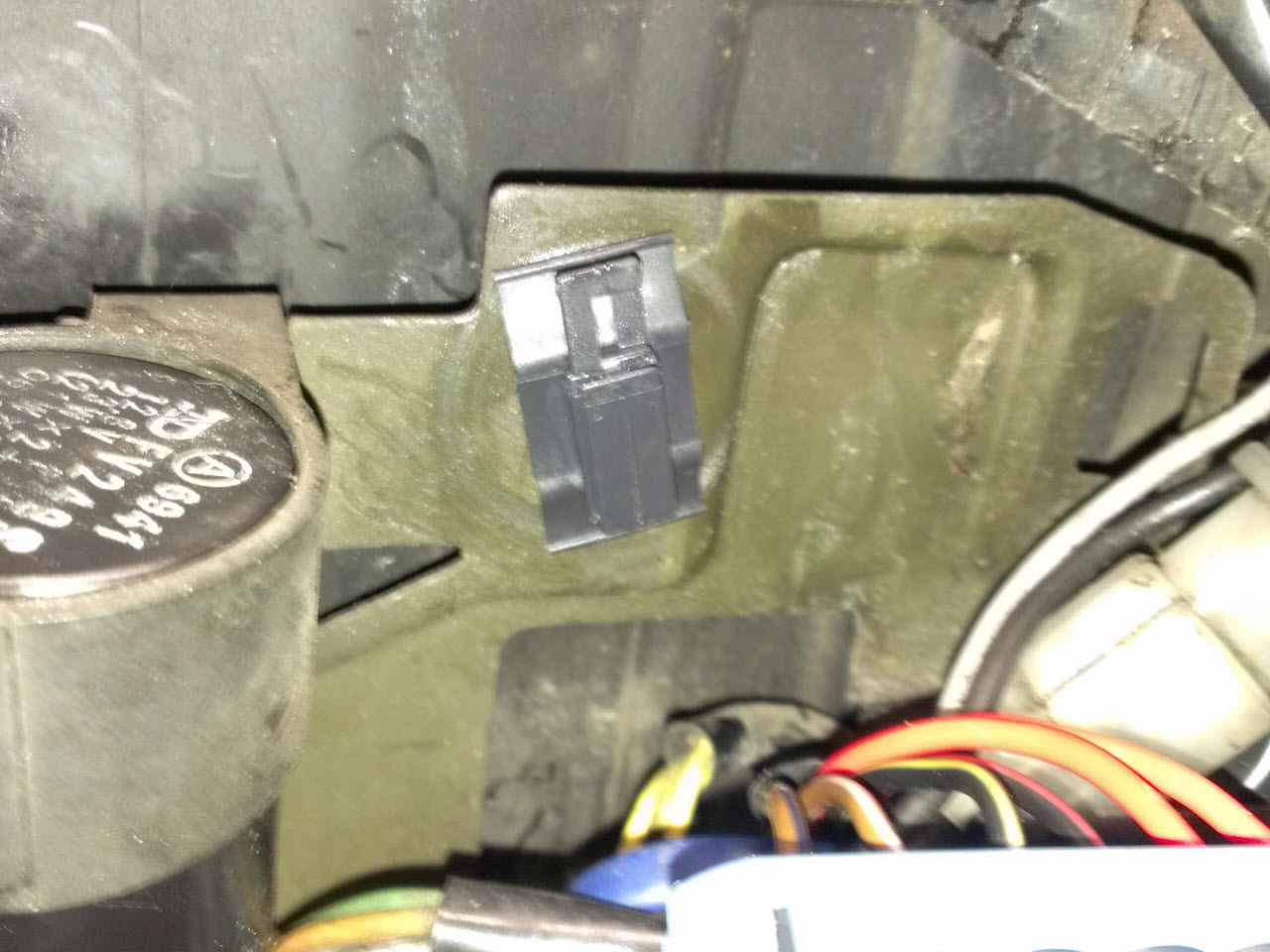
The fuseboxes came with a plastic mounting clip
The finished fusebox mounted neatly
AUX Fusebox
Since I was also installing headlight relays, and was planning to add a Powerlet socket in the near future, it made sense to create an additional fusebox.
The fusebox for the additional equipment was originally powered straight from the battery (unswitched) and found a place in the toolbox under the seat. As soon as I was going to swap the ignition out, however, I needed to find a different place for it.
For version two of the fusebox, I added one switched circuit, and two unswitched ones. It was moved next to the battery. The same relay also houses a switched connection for the ignition, and is mounted under the seat.
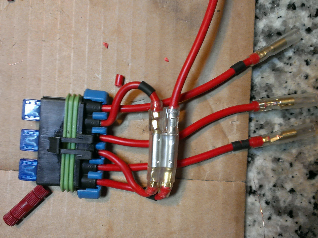
The finished AUX fusebox, version 1
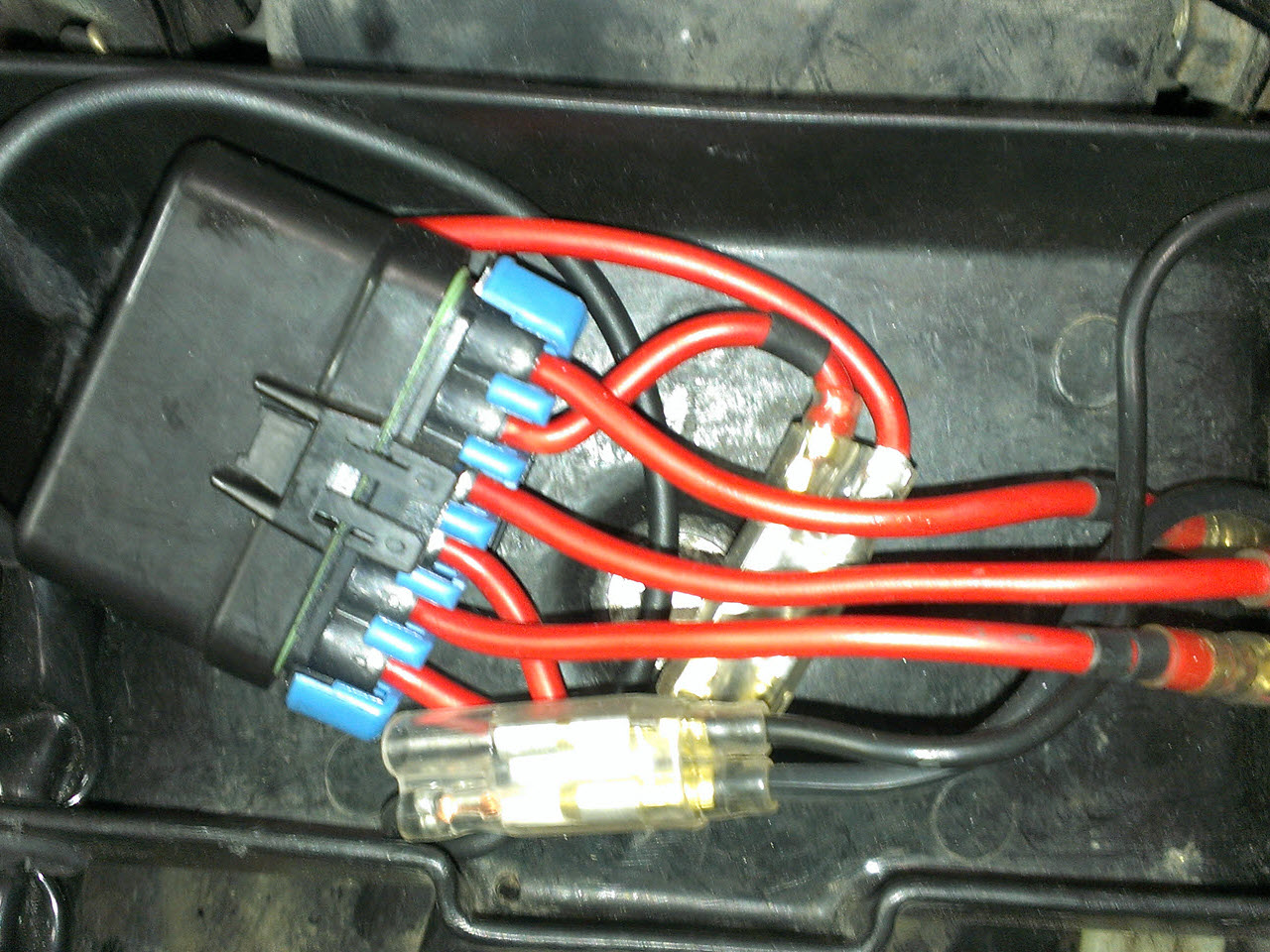
It was mounted in the toolbox under the seat, but later on needed to make room for the ignition
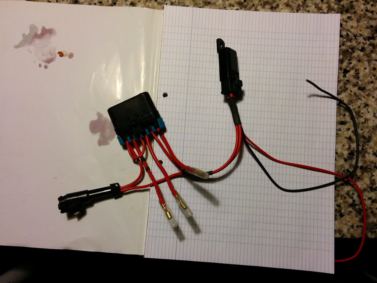
The finished version 2
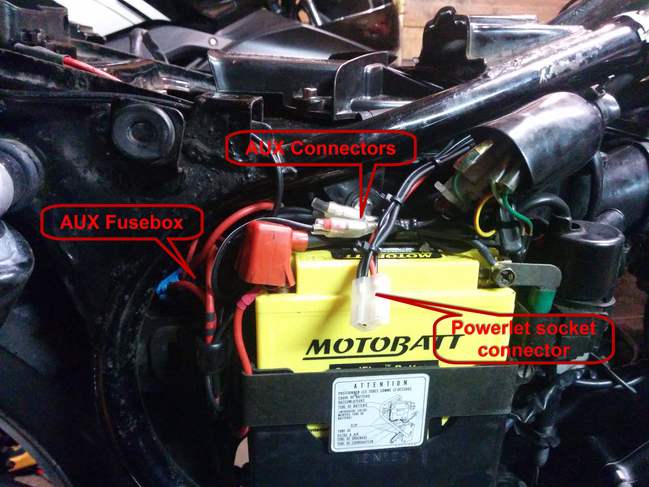
A quick explanation on how things are mounted
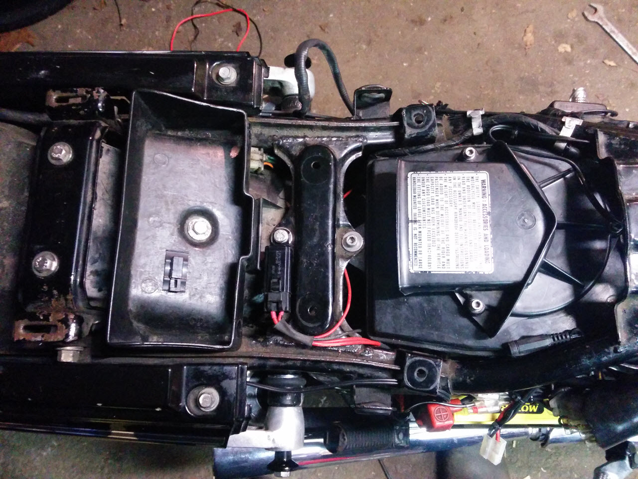
Top view, with the relay next to the toolbox
Headlight Relay Mod
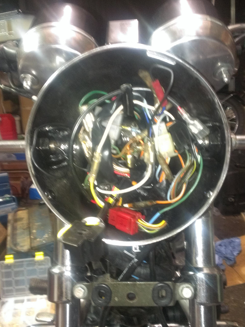
Remind me to take a decent picture of the full bucket
As mentioned, the second fusebox was used to power an Eastern Beaver headlight relay kit. This provided 12V straight to the headlight, through heavy gauge wire and improved visibility enormously. I was baffled by the sudden increase in light output from the 35/35W sealed beam!
There is almost no room in the headlight to store the stock cabling, adding two relays to that makes putting it together an art form. Later on, the sealed beam decided to die, so I had to source a replacement. I bought a horrible chinese knockoff CB250 headligh assembly with an H4 bulb, which makes fitting everything in the headlight even more difficult. Since the increased light output of the 55W H4 bulb is nice, I am now looking for a Honda reflector. The quality of the knockoff is miserable.
Turn Signal Relay Replacement
The original blinker relay was still working, but it had a tiny but dangerous flaw. When I wanted to turn on the turn signal, the relay would start in the "off" stand, and then the turn signal would light up. This meant that one "beat" of the turn signal was skipped. Sometimes, when lane changing, this meant that the blinker would only turn on while I was already starting to change lanes, a very dangerous situation. A cheap, universal, 2-wire relay was sourced as a replacement. Turn signals now work as expected, and start to blink immediately when the button is pushed. Since it's load-independent, I won't have to change the relay again if I later on decide to use LED bulbs.
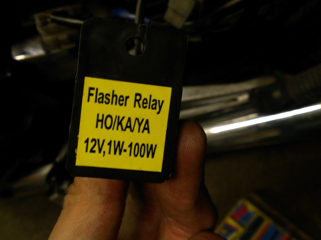
No brand, but a pretty decent description
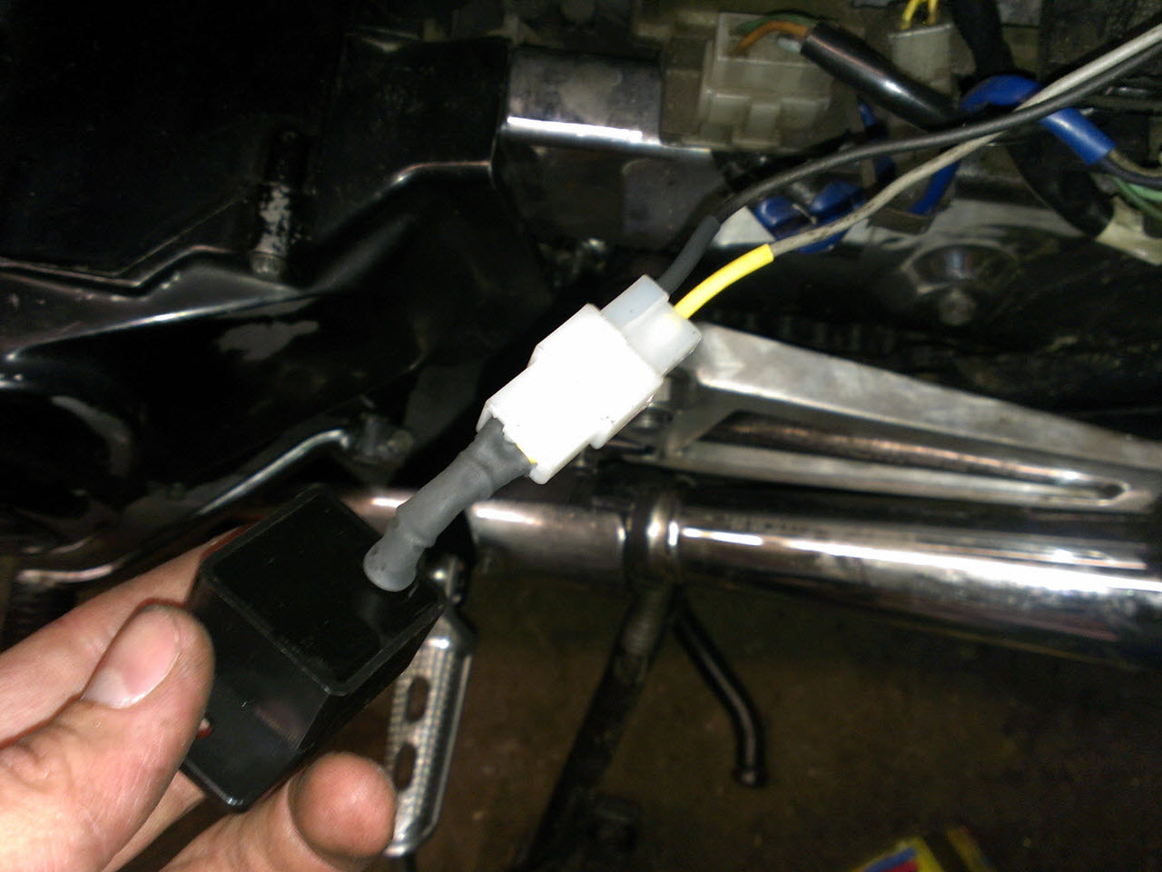
A breeze to install onto the original connector
Phase Two: Stator and R/R Swap
The original ignition system dedicated two coils on the stator solely for the CDI box. (For the full explanation, check the ignition thread.)
These coils became obsolete as soon as I switched to the Ignitech ignition. I could either short the leads coming off these coils and be done with it, or I could try to have the stator rewound and get the full power output.
I read that it could be done, but did not find anyone who could provide me with hard evidence. I found a small company in the Netherlands, Sevior, whose owner specializes in the maintenance and rewinding of electro-motors, stators and whatnot. Hans was willing to help me with the experiment.
He noticed that rewinding the original stator would not be ideal, and suggested to rewind a GL1000 stator for me, which would be a near direct swap.
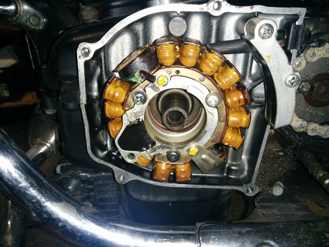
Stock stator. Note the odd coils on opposite sides, those are for the CDI
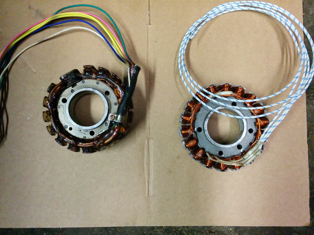
Old and new
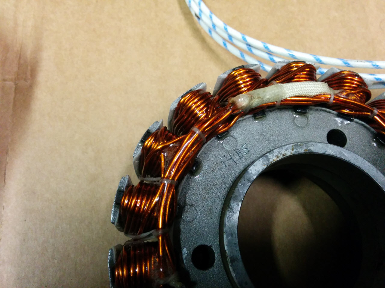
Detail of the beautiful wiring
Unfortunately, I immediately ran into an issue. The stator was just a mm or two too thick. The crankcase has two protrusions around the rotor mounting point, and the stator jammed on these two points. If I tried to mount washers under the stator, the rotor would rub on the stator screws.
I shipped that stator back, and Hans countersunk the bolt holes, and provided as second GL1000 stator, that was rewound thinner. I ended up mounting the second, thinner stator. Unfortunately there are no pics of the second stator while mounted. As the whole mounting process went by in a haze I forgot to take pictures.
Several things went wrong during the installation endeavour, check the goofs page.
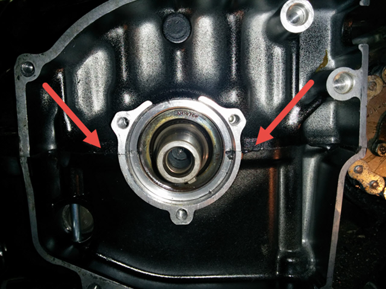
Indicated are the points where the stator wiring made contact with the crankase
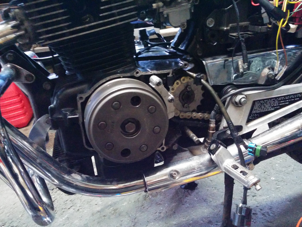
The rotor mounted again. I used glass fibre cable sheet to protect the wiring
The bike would now have an estimated 230watts of power, compared to the stock 170W (on a good day), this is a significant improvement. The stock regulator would not be able to cope with the added output for a very long time.
One of the mods that a lot of other bike owners do is to upgrade the regulator/rectifier to a modern, MOSFET r/r unit. The Shindengen FH012AA or FH020AA (the newer version) units are pretty common for this mod. The procedure for them is well-documented and they are always for sale on ebay, but at a steep price, so I started to look for a secondhand one. I discovered the Yamaha FJR1300 uses the FHA020AA, and is an extremely common bike around here. It did not take long for me to find a cheap secondhand R/R unit at a junkyard.
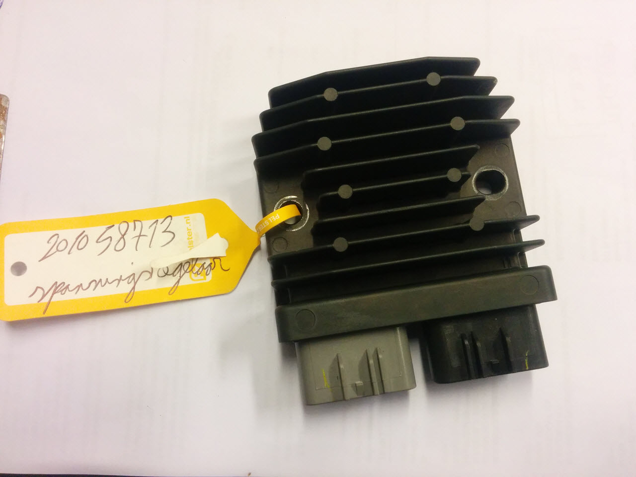
"New to me" regulator
The bike was getting more and more stuff added to it, so I started to get into trouble finding a mounting spot for everything. I was able to squeeze the much bigger R/R unit into the stock location by drilling a hole and shaving some metal from both the R/R unit and the frame.
This way the vibration damping of the stock bracket is kept. The connectors stick out about a cm at the bottom, but it is barely noticeable. I connected the unit to the stock cabling, but also added a second set of cables that run straight to the battery.
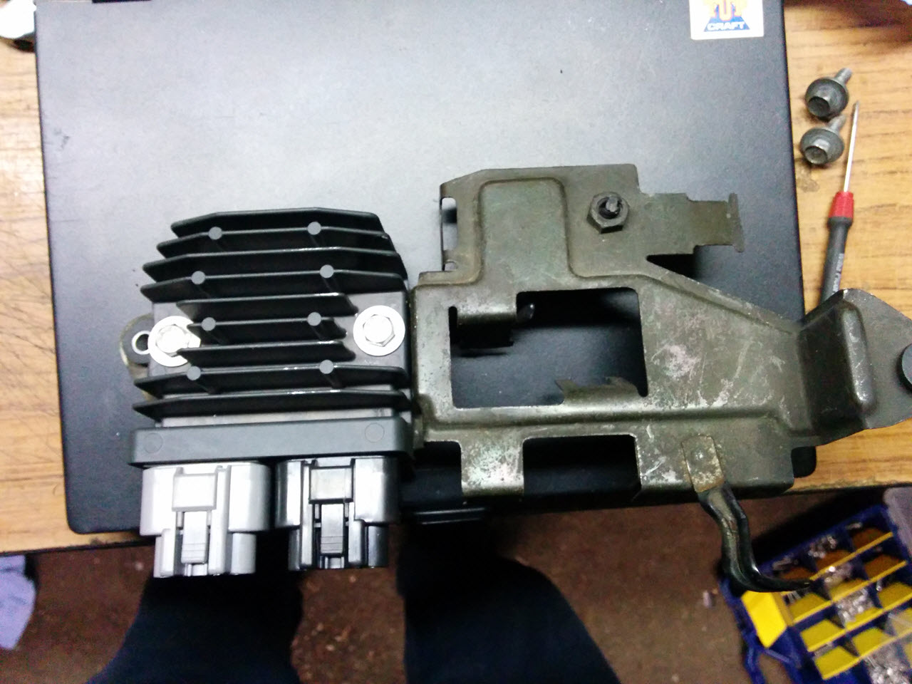
A tight squeeze in the original mounting location. Had to drill 1 hole
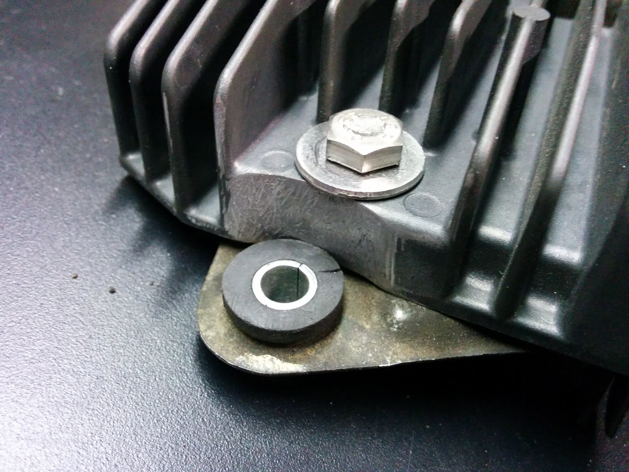
I shaved some material from the heatsink to make it clear the rubber dampers
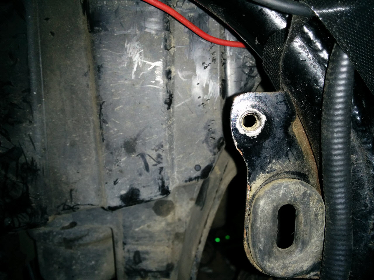
Some material was also filed off the frame tab
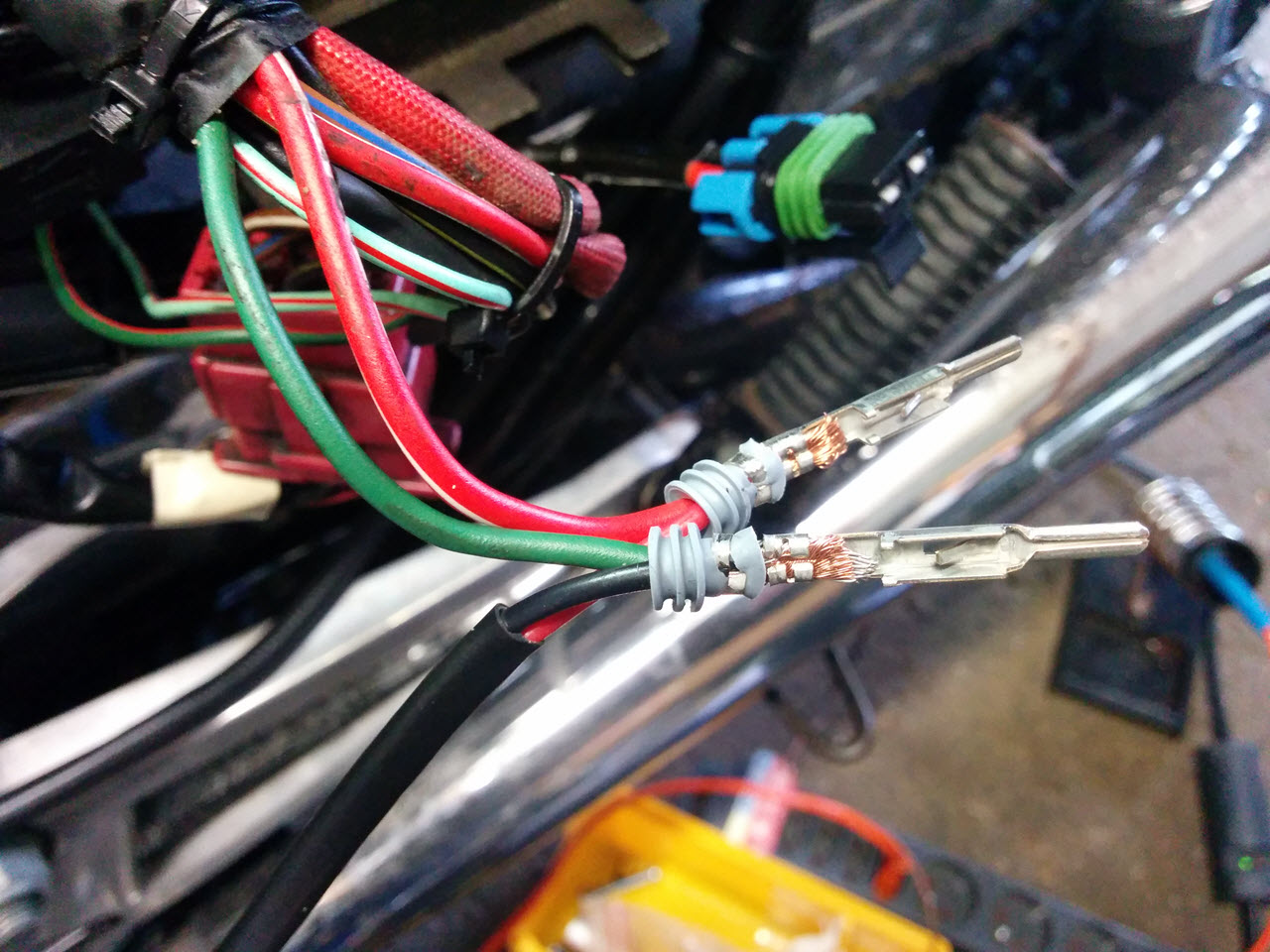
The second set of cables (bottom) goes straight to the battery
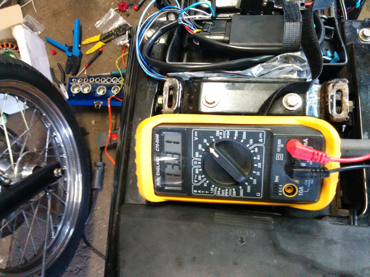
The voltage is extremely stable now. 13.81 at idle right after starting